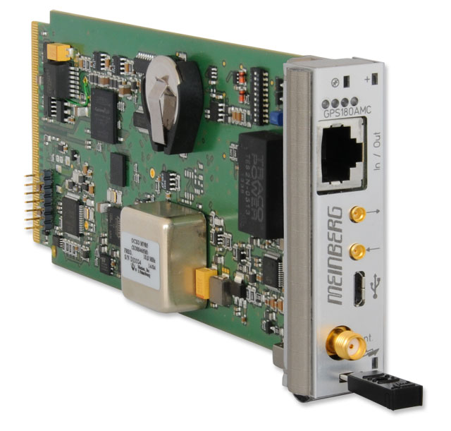
GPS180AMC: AdvancedMC Satellite Clock
Key Features


- Single lane (x1) PCI Express (PCIe) interface, PCI Express r1.0a compatible, Fat Pipe Region, Port 4, Data format: binary, byte serial
- USB 1.1 / USB 2.0 full-speed, Micro USB connector
- Plug and Play
- Included GPSANTv2 antenna uses downconverter technology to enable long transmission routes of up to 1100 m (1200 yards) -- with Ultraflex H2010 cable
- Programmable clock frequencies for TCLKA and TCLKC: 8kHz, 1.544MHz, 2.048MHz or 19.44MHz
- Driver software for all popular operating systems
- Including GPS antenna, 20m standard cable and manual on USB key
Product Description
Management
Complete units, as defined in the AMC standard, e.g. MicroTCA, are extremely flexible when it comes down to the data- and clock pulse interfaces used in-between the assembly groups. To ensure correct management of all resources, every system comes with a "Shelf Management Controller" (ShMC), or "MicroTCA Carrier Hub" (MCH), who ensures error-free functioning of the overall system, as well as of each assembly group. To do so the MCH communicates with a "Module Management Controller" (MMC) when the system is turned on or an AMC card is plugged into an operating system. The MMC is mandatory for every card, as specified in the AMC standard. In addition to providing the data- and/or clock pulse paths requested by the AMC card the Management Controller also ensures trouble-free plug and remove of modules in an operating system (Hot Swap).
To communicate with a system’s CPU, the GPS180AMC uses an "x1 PCI Express Interface (PCI Express r1.0a)" in the "Fat Pipe Region, Port 4".
Clock Pulse System
AdvancedMC defines a system to distribute (reference-) clock pulses and allows the construction of hierarchical clock pulse structure which is important especially in the telecommunication field. The GPS180AMC Module realizes the topology "SONET/SDH/PDH System Timing Module" as defined in the AMC standard:
The clock pulse signals (Direction: Out from Module) provided by the GPS180AMC are derived from the assembly group’s master oscillator. At GPS synchronization the master oscillator is being adjusted to the set point frequency and determines the free running qualities in case of a failure of the GPS receiver.
Hot Swap
AMC Modules can either be inserted or removed from the MicroTCA system while operating. The hot swap ability is realized by a lever mechanism (AMC Handle) including a micro switch, a status LED (blue LED), and the communication between the management controllers.
Characteristics
| Receiver Type | 12 channel GPS C/A-code receiver |
| Status Indicators | The Status LEDs "LED1" (out of service, red) and "LED2" (Heartbeat/Healthy, green) as specified in the AMC standard are positioned on the upper side of the front panel. When the Management Controller of the GPS180AMC detects a failure, the red "out of service" LED is activated. For example, if the pay load supply voltage is too high/low or if one of the temperature sensors of the GPS180AMC detect a too high ambient temperature.
As long as all cyclical hardware- and firmware audits of the MMC come out positive, the green "Heartbeat/Healthy" LED blinks. As soon as one of the tests shows a negative result, the LED2 is turned off and the red LED1 glows permanently. |
| Type of Antenna | Included GPSANTv2 antenna with innovative downconverter technology that allows transmission routes of up to 300 m using RG58 cable, 700 m using RG213 cable, and 1100 m using H2010 Ultraflex cable |
| Synchronization Time | Max. 1 minute in normal operating conditions
Max. 25 minutes (average 12 minutes) upon first initialization or in the absence of saved satellite data |
| Frequency inputs | 1 x 10MHz, max 5 Vpp, AC coupling
MMCX jack at the front panel |
| Frequency Outputs | 1 x TTL into 50 Ohm
female MMCX connector in the front panel default: 2.048MHz programmable: 8kHz, 1.544MHz, 2.048MHz, 10MHz, 19.44MHz |
| Precision of timebase |
Accuracy of time:
better than +/- 100 nsec after synchronization and 20 minutes of operation better than +/- 2 µsec during the first 20 minutes of operation |
| Interface |
Terminal Interface:
USB 1.1 / USB 2.0 full-speed, Micro USB connector
Serial Interface: Asynchronous serial interface (RS-232) COM1, I/O RJ45 jack Baud rate: 300 to 19200 Default: 19200, 8N1, Meinberg Standard Telegramm, per second |
| Electrical Connectors | Female SMA Antenna connector
Clock input: female MMCX connector in the front panel Clock output: female MMCX connector in the front panel |
| PC Interface | Single lane (x1) PCI Express (PCIe) interface
PCI Express r1.0a compatible Fat Pipe Region, Port 4 Data format: binary, byte serial |
| Backup Battery Type | Upon loss of power supply to card, the hardware clock runs independently using the on-board quartz oscillator. Almanac data remains stored in battery-backed RAM Life time of lithium battery min. 10 years |
| Operating Voltage | 12V Payload Power, 3.3V Management Power, 8W typ. |
| Board Type | Single, Mid-Size AMC Module, 181.5mm x 73.5mm x 18.96mm |
| Supported Temperature | 0 to 55 °C |
| Supported Humidity | Max. 85 % (non-condensing) at 40 °C |
| Warranty | Three-year warranty |
| Options |
Oscillator upgrade:
|
| RoHS Status of Product | This product is fully RoHS-compliant. |
| WEEE Status of Product | This product is handled as a B2B (Business to Business) category product. To ensure that the product is disposed of in a WEEE-compliant fashion, it can be returned to the manufacturer. Any transportation expenses for returning this product (at end-of-life) must be covered by the end user, while Meinberg will bear the costs for the waste disposal itself. |
Downloads
Data Sheet
Short Info Sheet
Manuals
- For drivers, SDKs, tools and utilities, please check our Download Section