GPS165: Satellite Receiver with integrated time code generator (DIN Mounting Rail)
Key Features


- Programmable pulses and switching times,
Time code or serial time string configurable for optocoupler outputs - Two RS-232 interfaces, one RS-485 interface
- DCF77 simulation
- Modulated and unmodulated IRIG-B or AFNOR Outputs
- Included GPSANTv2 antenna uses downconverter technology to enable long transmission routes of up to 1100 m (1200 yards) -- with Ultraflex H2010 cable
- DC-insulated antenna circuit
- Remote control and monitoring with included software Meinberg Device Manager (COM 0)
- Aluminium profile case for 35mm DIN mounting rail
- Flash-EPROM with bootstrap loader
Product Description
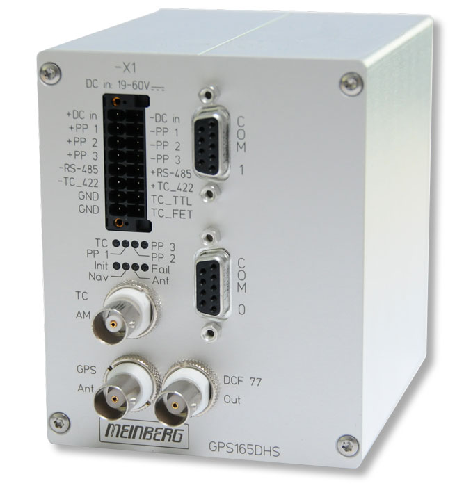
The GPS165 is designed for mounting on a DIN rail. The front panel integrates eight LED indicators, a terminal block, two DSUB and three BNC-connectors. The receiver is connected to the antenna/converter unit by a 50 Ohm coaxial cable with length up to 300 m (when using RG58 coax-cable). The antenna/converter unit is powered via the antenna cable. It is possible to connect up to four receivers to one antenna by using an optional antenna diplexer.
Pulse Outputs
The pulse generator of the satellite controlled clock GPS165 provides three independant channels and is able to generate a multitude of different pulses, which are configured with the Meinberg Device Manager software. The pulse outputs are electrically insulated by optocouplers or PhotoMOS relays and are available at the terminal block.
Asynchronous Serial Interfaces
One RS-485 serial interface and two RS-232 serial interfaces are available to the user. The corresponding parameters can be set up by Meinberg Device Manager using serial port COM 0.
Characteristics
| Receiver Type | 12 channel GPS C/A-code receiver |
| Status Indicators | Fail-LED shows that the internal timing has not been synchronized or that a system error occurred Nav-LED shows that the calculation of the position has been achieved after reset |
| Type of Antenna | Included GPSANTv2 antenna with innovative downconverter technology that allows transmission routes of up to 300 m using RG58 cable, 700 m using RG213 cable, and 1100 m using H2010 Ultraflex cable |
| Control Elements | Four LEDs to display the status of the programmable outputs and the time code output Four LEDs to display the status of the receiver (Init, Nav, Fail, Antenna) |
| Synchronization Time | Max. 1 minute in normal operating conditions
Max. 25 minutes (average 12 minutes) upon first initialization or in the absence of saved satellite data |
| Accuracy of Pulse Outputs | Better than ±100 nsec after synchronization and 20 minutes of operation better than ±3 µsec during the first 20 minutes of operation |
| Interface | Two independent serial RS-232 interfaces COM 0 and COM 1, COM 2 as RS-485 interface |
| Serial Time String Output | Baudrate: 300 to 19200 baud Framing: 7N2, 7E1, 7E2, 8N1, 8N2, 8E1, 801 Time strings: Meinberg Standard, Meinberg GPS, SAT, Uni Erlangen (NTP), NMEA0183, Computime, Sysplex-1, SPA, RACAL, ION, IRIG J |
| DCF77 emulation | Amplitude modulated 77.5 kHz sinewave carrier output level approximately -55 dBm (unmodulated) |
| Optocoupler outputs | 3 optocoupler outputs; UCEmax = 55V, ICmax = 50 mA, Ptot = 150 mW, Viso = 5000 V the following operating modes are possible for each channel: - free programmable cyclic or fixed pulses - timer mode; three 'ON'- and three 'OFF'-times programmable per day and channel - receiver state; synchronous state of the GPS-receiver is indicated - DCF77-emulation - Time code (IRIG/AFNOR) - Time string (time telegram of COM1) The switching state of each channel can be inverted, the pulse duration is settable in steps of 10 msec from 10 msec to 10 sec. The outputs can be enabled either: - always (immediately after reset) - only if receiver is GPS-synchronised |
| Supported Timecode Formats |
IRIG B002: 100pps, DCLS signal, no carrier, BCD time-of-year IRIG B122: 100pps, AM sine wave signal, 1 kHz carrier, BCD time-of-year IRIG B003: 100pps, DCLS signal, no carrier, BCD time-of-year, SBS time-of-day IRIG B123: 100pps, AM sine wave signal, 1kHz carrier, BCD time-of-year, SBS time-of-day IRIG B006: 100 pps, DCLS Signal, no carrier, BCD time-of-year, year IRIG B126: 100 pps, AM sine wave signal, 1 kHz carrier frequency, BCD time-of-year, Year IRIG B007: 100 pps, DCLS Signal, no carrier, BCD time-of-year, year, SBS time-of-day IRIG B127: 100 pps, AM sine wave signal, 1 kHz carrier frequency, BCD time-of-year, year, SBS time-of-day IEEE1344: Code according to IEEE1344-1995, 100pps, AM sine-wave signal, 1kHz carrier, BCD time-of-year, SBS time-of-day, IEEE1344 expansion for date, time zone, daylight saving and leap second in Control Functions segment C37.118: Like IEEE1344 - with inverted sign bit for UTC offset AFNOR: Code according to NFS-87500, 100pps, AM sine-wave signal, 1kHz carrier, BCD time-of-year, complete date, SBS time-of-day |
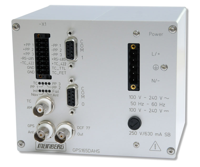
| Electrical Connectors | 16-pin terminal block for connecting the pulse/switch outputs and the power supply BNC female connectors for DCF77-simulation (AM-modulated 77.5 kHz carrier frequency) and modulated timecode output (3 Vpp into 50 ohm) female Sub-Min-D connectors for serial interfaces and unmodulated timecode outputs |
| Antenna Connector | BNC connector |
| Power Consumption | ca. 5 W |
| Backup Battery Type | Upon loss of power supply to card, the hardware clock runs independently using the on-board quartz oscillator. Almanac data remains stored in battery-backed RAM Life time of lithium battery min. 10 years |
| Operating Voltage | GPS165DHS: 20-60 V DC GPS165DAHS: 100-240 V DC / 100-240 V AC (50-60 Hz) |
| Firmware | Flash-EPROM, bootstrap loader |
| Physical Dimensions | GPS165DHS: 105 mm x 85 mm x 104 mm (h x w x d) for 35mm DIN mounting rail GPS165DAHS: 105 mm x 125,5 mm x 104 mm (h x w x d) for 35mm DIN mounting rail |
| Supported Temperature | Operational: 0 - 50 °C (32 - 122 °F)
Storage: -20 - 70 °C (-4 - 158 °F) |
| Supported Humidity | Max. 85 % (non-condensing) at 40 °C |
| Options | Photo-MOS-relay-outputs (instead of optocouplers): Umax = 250 V AC/DC peak, Imax = 150 mA, Ptot = 360 mW, Viso = 1500 V |
| Deployment in special environments | The GPS165 and its variants are already deployed to numerous customers in the power industry. They are used for electrical substation synchronization all over the world, for example in South America, the USA and Europe. This product is therefore suitable to work under harsh conditions and still provide reliable and accurate synchronization. |
| RoHS Status of Product | This product is fully RoHS-compliant. |
| WEEE Status of Product | This product is handled as a B2B (Business to Business) category product. To ensure that the product is disposed of in a WEEE-compliant fashion, it can be returned to the manufacturer. Any transportation expenses for returning this product (at end-of-life) must be covered by the end user, while Meinberg will bear the costs for the waste disposal itself. |
Downloads
Short Info Sheet
Manuals
- For drivers, SDKs, tools and utilities, please check our Download Section