

Powerline Frequency Monitoring
Mains Frequency Monitoring
Millihertz Resolution
The FDM module uses a GPS synchronized 10 MHz signal as a reference and calculates a running average over either 100 ms or 1 s. Other powerline frequency related measurements are also available including: Frequency Deviation (the difference between the actual frequency and the nominal frequency, either 50/60 Hz), Powerline Time (a separate timebase that is initialized using GPS time and then advanced based upon the 50/60 Hz frequency), and Time Deviation (the difference between the powerline time and the reference time (GPS time). The resolution of the frequency measurements is 0.001 Hz.
Wide Input Voltage Range
The LANTIME FDM module accepts a wide range of input voltages from 70-270 V AC.
Web-Based Data Visualization
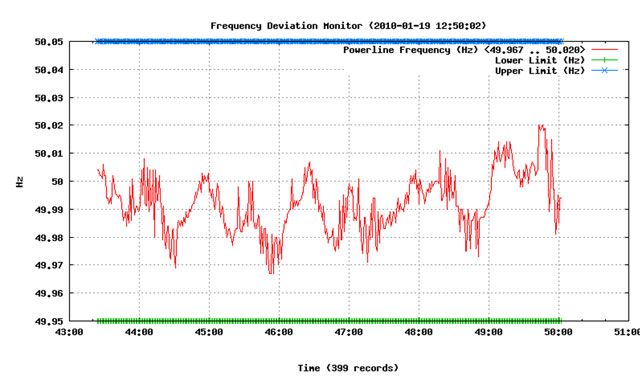
The powerline frequency measurements can be displayed in a constantly updated diagram in PNG format. This can be easily embedded into web pages on other systems or accessed directly on the LANTIME Time Server for a quick reference.
FDM measurement data transmitted to the network
The FDM software in the LANTIME FDM module provides the FDM measurement data to receivers on the network, data logging computers, or wall mounted displays in control rooms. The LANTIME FDM design allows two LANTIME servers to provide redundant data feeds for every receiving network host. If one LANTIME unit fails, the backup LANTIME automatically intervenes and ensures that the receiver is updated with the latest measurement values.Data is sent over a TCP connection to up to 15 different IP addresses per LANTIME unit. The default TCP port 10001 can be changed individually for each receiving application or display, allowing one central data recording server to receive FDM data from an unlimited number of LANTIME units. This allows for a highly redundant solution by receiving data from two redundant LANTIME measurement systems in parallel, thus ensuring that data is still written into a database when one of the measurement devices fails. It also facilitates the configuration of distributed measurement systems, where an application receives data from a large number of LANTIME FDM systems installed in multiple locations.
Implementation of FDM measurement in your own applications is simple; listen to incoming TCP network connections from LANTIME devices. The LANTIME FDM software will attempt to establish a connection to a list of target IP addresses, and if a configured receiver does not accept the connection or is not reachable, will periodically retry to establish the connection.
Data is provided in different formats; two fixed strings and individually configured custom strings (which can include all the standard values), or optionally combined with static text. Updated data is transmitted at the start of every second (delivering the data of the past second).
The standard data format offers the following values:
- Powerline Frequency (FF.xxx Hz)
- Frequency Deviation (±FF.xxx Hz)
- Reference Time (HH:MM:SS)
- Powerline Time (HH:MM:SS.mmm)
- Time Deviation (±MM:SS.mmm)
The extended data format includes all the information of the standard format plus nine intermediate measurements of the powerline frequency, measured in 100ms intervals.
The customized string format can be defined individually for each configured receiver, or for a group of receivers. You can also change automatically between different formats at predetermined intervals. This allows you to set a configuration which sends the current Powerline Frequency for 10 seconds, then sends the Powerline Time for 5 seconds, and then the Time Deviation value for 5 seconds, repeating the sequence continuously.
Two different wall mounted display models are currently offered which can be configured to display the FDM data:
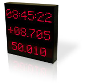
DU35K/FDM/ND
Three line configuration to display three different measurements at the same time.Each line can be set up to display a different measurement. This triple display yields a space-saving indication of three current measurements. The DU35K display requires the Standard FDM Format, and you can select which measurement is assigned to each of the three rows by means of the display menu and the pushbuttons at the rear of the display.
DU70/FDM/ND
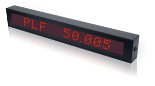 Single line display with automatic display toggle feature
The single line display can be configured to periodically change its display content and toggle between different values such
as Powerline Frequency, Time Deviation, Reference Time, etc. The display content can be configured on the LANTIME units by
combining static text with placeholders for the different FDM values.
Single line display with automatic display toggle feature
The single line display can be configured to periodically change its display content and toggle between different values such
as Powerline Frequency, Time Deviation, Reference Time, etc. The display content can be configured on the LANTIME units by
combining static text with placeholders for the different FDM values.
For example:
"PLF %PLFREQ" would show "PLF 50.005" on the
display indicating the Powerline Frequency of 50.005 Hz. This could also indicate the data source by defining a custom format
such as "[A] %PLTDEV" on the primary LANTIME device and "[B] %PLTDEV" on the backup unit.
Redundancy for the data display is achieved simply by adding another display to a system of multiple LANTIME units. Since only one incoming TCP connection is supported by the display, the first LANTIME that is capable of establishing a connection will provide the data feed while the backup systems periodically retry to connect to the display. Immediately upon failure of the active data feed provider, the display is available for a new incoming connection and at that point accepts the backup LANTIME connection.
Manually Synchronized Time Deviation Values
In order to synchronize the time deviation values on multiple LANTIME units, the end user can easily set the time deviation value to an arbitrary number, either by an SSH connection via SCP or FTP file transfer, or by using SNMP.
Measurement Log File Storage
Measured values are stored in data files on a volatile RAM disk on the LANTIME and are available for transfer to permanent storage using FTP or SCP. This is highly recommended in order to avoid data loss in the event of a hardware failure.
Automatic Monitoring of Powerline Frequency
It is possible to define an upper and lower limit for the powerline frequency and receive alarm messages (email, syslog, SNMP traps) when the LANTIME device detects that the frequency measurement value is outside the acceptable range. Triggers can also be set for notifications for other events such as GPS reception loss, reboot, and configuration changes.
Full SNMP V1, V2c and V3 support
All FDM data values can be retrieved using SNMP GET commands. Additionally, the LANTIME notification system allows you to define up to three SNMP trap receivers to receive SNMP traps whenever the powerline frequency exceeds the configured maximum/minimum value. Other SNMP objects provide information about GPS synchronization status, NTP status and general system parameters such as CPU utilization, network traffic, and so on.
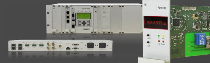
MEINBERG FDM Product Range
Deviation Monitor module (FDM)
Network Time Servers available with integral
Frequency Deviation Monitor module (FDM):
Network Displays Supporting FDM:
The Meinberg FDM module is a cost effective, powerful and robust solution to monitor and record powerline frequency performance. This module also enables the user to receive alarm notifications if the frequency falls outside preset limits, and to easily log system performance data to fulfill regulatory compliance requirements.
The FDM module is designed as an option for the Meinberg LANTIME M-series and LANTIME IMS-series. Each Time Server equipped with the FDM module offers the full LANTIME feature set, including highly accurate and reliable GPS synchronized stratum 1 NTP time and redundant network interfaces.
All FDM products support both 50Hz and 60Hz powerline frequencies!
