AMX21/HS: Antenna Switch Unit for all Meinberg's GPS, GPS/GLONASS L1 and LF Antennas.
Key Features


- Available as AC (AMX21DAHS) and DC variant (AMX21DHS)
- Easy mounting
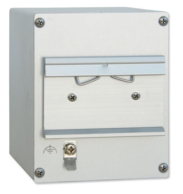
- Aluminium profile case for 35mm DIN mounting rail
- Automatic or manual switching between two connected GPS Antennas
Product Description
Function:
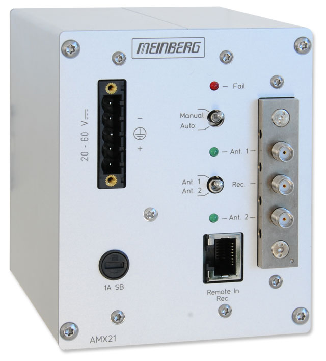
The AMX21/HS switching unit expands the redundancy concept on to the antenna. A receiver can now be connected with two antenna/converter units. If an antenna fails or provides poor reception, the switchover to the other antenne will be done either automatically or manually, depending on the pre-selected mode.
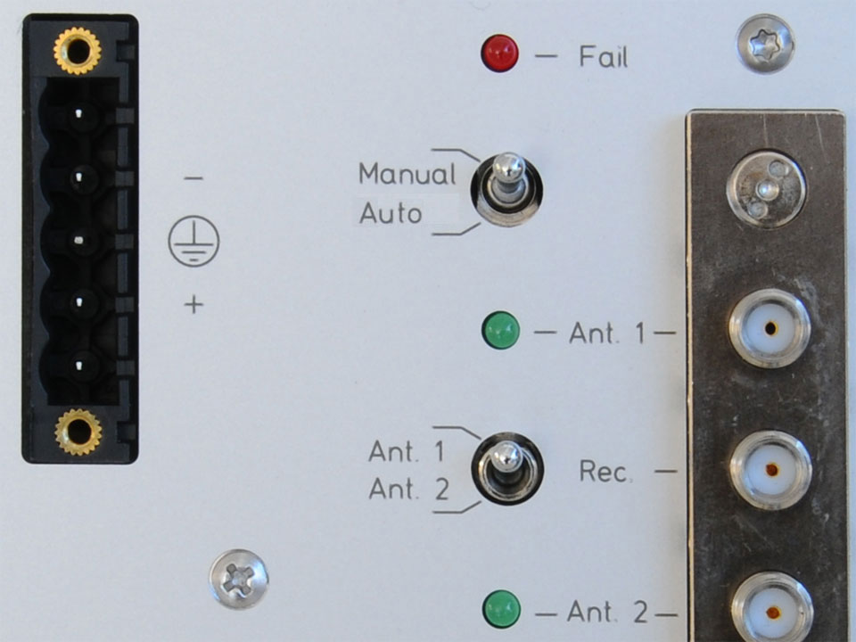
The switchover between the two antenna/converter units can occur manually as well as automatically. A switch is available for choosing between the two operating modes. In the "Manual" mode a second switch can be used for direct switching between the two antennas.
In "Auto" mode the switching between the antennas depends on the number of visible satellites. This information is transmitted via time string (NMEA GGA format). The NMEA Time String is generated by the connected GPS receiver.
Characteristics
| Status Indicators | Two LEDs show which antenna is chosen
FAIL-LED shows that no serial string is available |
| Control Elements | Two switches for choosing the operating mode and the antenna |
| Electrical Connectors |
|
| Bandwidth | DC to 6 GHz |
| Operating Voltage | 20...60 V DC 100...240 V DC 100...240 V AC, 50...60 Hz |
| Operation Voltage Antenna | 5...18 V DC |
| Form Factor | Fischer aluminium housing for DIN mounting rail |
| Physical Dimensions | 105 mm x 85 mm x 104 mm (H x W x D) |
| Supported Temperature | 0...45 °C |
| Supported Humidity | Max. 85 % (non-condensing) at 40 °C |
| Warranty | Three-year warranty |
| RoHS Status of Product | This product is fully RoHS-compliant. |
| WEEE Status of Product | This product is handled as a B2B (Business to Business) category product. To ensure that the product is disposed of in a WEEE-compliant fashion, it can be returned to the manufacturer. Any transportation expenses for returning this product (at end-of-life) must be covered by the end user, while Meinberg will bear the costs for the waste disposal itself. |
Downloads
Short Info Sheet
Manuals
- For drivers, SDKs, tools and utilities, please check our Download Section